


- OTA – wireless performance testing
- Why is testing your wireless performance so important?
- When is OTA testing necessary?
- Does your device require OTA testing?
- Development of Over-the-Air, OTA Testing
- Anechoic test chambers
- Near and far-field
The number of people who connect their wireless devices to wireless networks has increased exponentially during the last few years. Users expect their devices to work perfectly everywhere and carriers need to answer these expectations with better reliability. Therefore, OTA (Over-the-Air) testing is important to evaluate the reliability and wireless performance of the wirelessly connected devices.
Over-the-Air – wireless performance testing
OTA, Over-the-air testing, is all about the radio signals. OTA testing is an approach used to measure the wireless performance and reliability of a wireless device via the antenna. The radio signal of the wireless device is examined in various ways by simulating use cases in real-life conditions. To achieve this, the device under test (DUT) is set down in a test environment inside a test chamber. The test chamber is isolated from any outside signals. The goal is to verify the wireless performance and that the device responds as intended to the test conditions.
When developing new wireless products and solutions, the characteristics of its embedded antennas are optimized for different antenna parameters. Several factors affect the wireless performance of your device. The final design is always a result of multiple compromises in the functional requirements the product must meet. Some factors like choice of materials, placing of components and intended use case affect device performance drastically.

Why is wireless performance testing so important?
OTA tests are done to evaluate and verify wireless system performance. It also helps to meet the requirements set by the network operators.
More specifically OTA testing:
- Highlights potentially costly design errors
- Allows for benchmarking between product variants and competing products
- Secures meeting rigorous product development schedules
- Secures customer and brand value
During the development process of any IoT (Internet of things) or M2M (machine to machine) device, the design and configuration of selected antennas need to be tested. This is done to ensure that the device performs as intended, for example with battery-powered IoT devices that the power consumption remains reasonable. With the help of emerging new technologies, these devices are becoming more and more compact. As a result, antennas are placed near other antennas, displays, computer processors, high-speed memory, etc. All these can interfere and degrade the devices’ wireless performance. A good wireless connectivity is an important criterion for customers when choosing a device. Having a well-functioning device ensures customer value and builds trust in the brand.
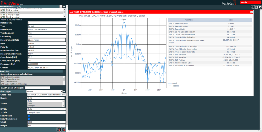
Thanks to OTA testing, device manufacturers and suppliers can make sure that their product has the best wireless performance. OTA testing assures that the products are ready to be sold on the market. Over-the-air testing entails the measurement of maximum radiated transmission power and sensitivity of the device. These together with OTA maximum data throughput measurements permit the evaluation of the radiation pattern.
Several factors can influence antenna performance, such as:
- Antenna pattern change
- Impedance mismatch loss
- Antenna detuning
- Self-interference
When is Over-the-Air testing necessary?
Over-the-air testing is required by large network operators and wireless industry organizations, to guarantee that the device antenna will function properly in their networks. This encompasses all common radio systems, such as 2G through 5G, WLAN and NB-IoT. Also, passive antenna measurements via OTA are important for antenna designers and manufacturers.
OTA testing is not required for CE, FCC, or ISED certification, however, most network operators expect device manufacturers to conduct independent OTA testing. Poor OTA performance would result in poor throughput in communication and potential access failure.
OTA performance measurement itself is regulated by several guidelines and specifications established by telecommunication authorities. When measuring any DUT, the tests usually follow prevailing telecommunication standards. The most common ones are the 3GPP (3rd Generation Partnership Project) and CTIA (Cellular Telecommunications Industry Association). For example, to enter markets in the US, wireless device manufacturers and suppliers need to understand the up-to-date requirements for over-the-air testing by the CTIA. Some unique tests also exist that are not in the scope of CTIA or 3GPP but are used by network operators.
Does your device require Over-the-Air testing?
Radio use is regulated in countries worldwide by national legislation. Manufacturers of radio products, capable of transmitting and receiving RF waves (e.g. phones, wearables, or any wirelessly connected equipment) need to follow this legislation. Also, to bring the product in the market, they may need the necessary certification.
These products include e.g.
- Internet-of-Things products
- Smartphones
- Portable computers
- Utilities management products
- Fleet management systems
- Robotics
- Mobile payment systems
- Positioning systems (GNSS)
- Private network systems for industrial use
- Inventory management systems
- Traffic control systems
- Connected health products
- Automation/monitoring products
- Wearables
- Vehicular wireless systems

Development of Over-the-Air, OTA Testing
OTA testing involves testing a wireless device over the air barrier layer via antenna, without any connected cables. Thereby incorporating the antenna to device performance.
1. Conducted testing vs Over-the-air, OTA testing
The traditional method of testing wireless devices has been through directly wired cables. Wired cables are (galvanic connections) connected to the devices’ temporary antenna connectors, which are ports used for conformance testing. This approach of testing is suitable for the most existing wireless performance tests. Since not only is it conveniently accessible, it is not vulnerable to radiated noise or interference in the test environment.
At the same time, there are some disadvantages in conducted testing. It does not take into account the wireless performance of the device’s antennas. Also, it overlooks problems that might appear in the antenna due to poor design or faulty construction. With the birth and advancement of multiband devices using multiple antennas and MIMO (Multiple Input Multiple Output) technologies, conducted measurements that bypass the antennas are no longer a good indicator of radiated OTA performance. That is why it is necessary to use other methods to assess antenna performance. Compared to conducted testing, OTA testing has the advantage of not needing to break down or alter the test device to conduct testing.
In FR1 frequency ranges (410Mhz-7125Mhz) most of the device performance testing has been traditionally done via conducted testing. However, with the increasing number of antennas and antenna elements in wireless equipment, this is becoming more and more impractical. With FR2 frequency ranges (24Ghz-53GHz) introduced in 5G NR (new radio), most of these tests are only able to be performed over-the-air via an antenna. Through 5G the practice of conducting OTA testing becomes more predominant. Performance tests previously conducted via cables in the older systems will also be performed over-the-air in the future.
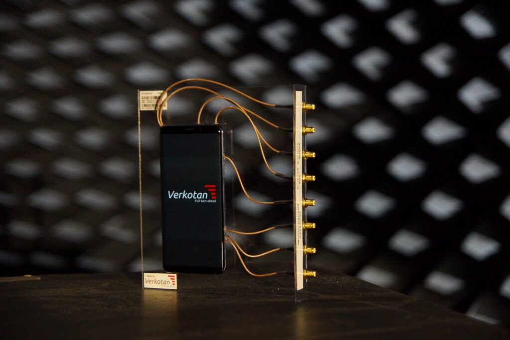
If you are interested in conducted testing and Verkotan phone RF modification, read our news about the 5G phone modification.
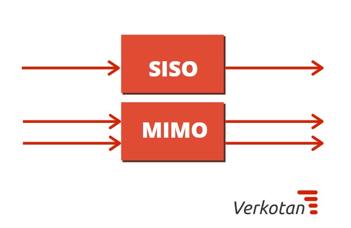
2. SISO OTA
In October 2001 CTIA published the first SISO (Single input single output) OTA test specifications, defining two metrics for the device: Total Radiated Power (TRP) and Total Isotropic Sensitivity (TIS). Total Radiated Power measures the total overall antenna power radiated by the antenna and is defined as the integral of the power transmitted in different directions over the entire radiation sphere. Later, within the 3GPP OTA specifications, Total Isotropic Sensitivity used by the CTIA was renamed Total radiated sensitivity (TRS), and the two terms are now used interchangeably. Total radiated sensitivity (TRS) is a measurement that signifies the reference sensitivity of the DUT averaged over all the directions.
Once a standardized OTA test process had been formed, device vendors and network operators could independently test and measure their existing equipment as well as new devices and compare radiated performance. This resulted in there being significant differences discovered in device performance that was the result of free space antenna performance. Moreover, CTIAestablished tests that included a head “phantom,” with the intention to emulate the electrical properties of a human head. These tests revealed further proof of performance differences between devices that were attributable to antenna design.
3. MIMO OTA
MIMO (Multiple Input Multiple Output) is a technology that lets radio signals to be sent and received using multiple antennas located in the device. The system uses multipath propagation to achieve a more efficient way to transmit RF signals. In this method by using different coding, the complex, high-power signal is split to multiple low-power signals and transmitted to the receiving device’s antennas from multiple different paths. When both the transmitting and receiving devices have multiple antenna ports and antennas, and multiple data streams are transmitted simultaneously to the receiving device using the same time/frequency resources, the peak throughput of a single user can double (2×2 MIMO), or quadruple (4×4 MIMO), and so on.
When testing MIMO devices over-the-air, the SISO OTA test methods and TRP and TRS metrics do not scale up to SIMO (Single Input Multiple Output) and MIMO conditions. When testing a DUT with receive diversity, the anechoic chamber test method of using a single angle of arrival (AoA) and single polarization presents the DUT with an unrealistic signal. The solution to this problem by the CTIA entails testing each receiving antenna in the DUT individually. While this approach is practical and thorough, it does not fully reflect the device’s performance in real-life conditions, where multiple simultaneous angles of arrival and polarizations exist.
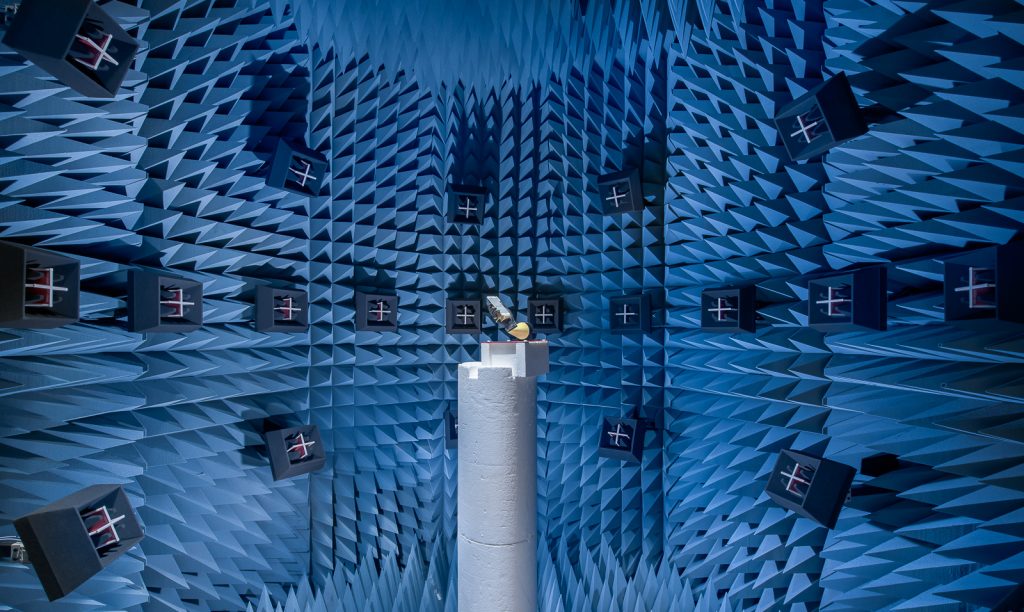
Anechoic test chambers
The aim of the Over-the-Air testing method is to simulate realistic radio wave propagation conditions that match real life as closely as possible. These tests are usually carried out in an anechoic chamber that is covered within with absorber material to reduce the signal reflections. Anechoic means without echoes, as in no RF waves are reflected back from the sides of the chamber. This absorber material commonly takes the shape of small pyramids, consisting of rubberized insulating foam that is saturated with conductible metals. Radio waves are absorbed by dissipating their energy when colliding with these pyramids. Anechoic chambers also function as faraday cages to shield them from external interfering signals.
The benefit of conducting measurements in a controlled lab environment compared to doing them in-field is that any noise that might interfere with testing is eliminated. The benefit of conducting measurements in a controlled laboratory environment compared to doing them in-field is that any noise that might interfere with testing is eliminated.
How does a wireless performance test chamber work?
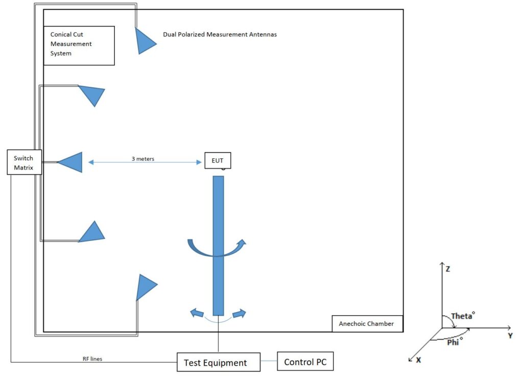
When a transmitted radio wave collides with an object, parts of it are diffracted, reflected, or absorbed. In an anechoic chamber, a radio channel emulator and multiple antennas placed at various angles are used to simulate these conditions, replicating real-life scenarios, such as urban and indoor surroundings within a controlled lab environment. These conditions include e.g. multipath propagation, noise, and interference.
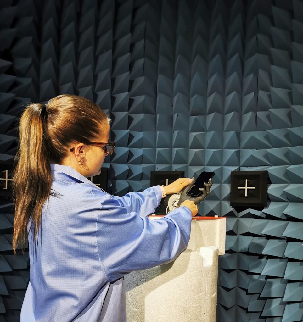
In anechoic chambers, the DUT is usually set down on a positioner, which enables the possibility of measuring the operating device from multiple angles, as well as multiple polarizations. The measurement uncertainty inside an anechoic chamber is defined as a small space within the chamber known as the “quiet zone”, where the DUT is placed. The size of the quiet zone correlates directly with the size of the anechoic chamber and inversely with the frequency of the test. This leads to most chambers having a goal of keeping a distance of three meters between the DUT and the probe antenna. The figure below shows an equipment-under-test placed in an anechoic chamber.
Near and far-field
The near field and far field are areas of the electromagnetic field around a transmitting antenna. Near-field and its associated non-radiation behaviors appear closer to the antenna, while far-field with its electromagnetic radiation behaviors are present at further distances. The near field and far field are illustrated in the figure below.
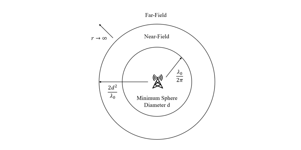
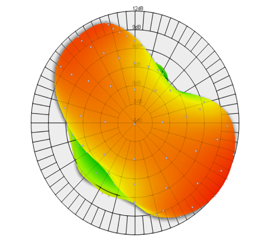
The radiation behavior of antennas is characterized by their far-field radiation pattern. The far-field distance is generally 2d^2/ λo (d = minimum sphere closing the antenna and λ = operating wavelength), where the transmitted spherical waves can be regarded as plane waves at the receiving antenna.
Large antennas operating at high frequencies e.g. antennas for satellite communications, base station antennas, etc.) form their far-field characteristics at a large distance from the antenna under test (AUT). This has a large effect on antenna measurement possibilities since to carry out far-field measurements in controlled indoor environments huge anechoic chambers would be required, which would be immensely expensive to manufacture and maintain.
An alternative approach is antenna near-field measurements using a near-field to far-field (NF-to-FF) conversion, where the far-field characteristics are calculated using software and necessary transformation algorithms. This approach considerably reduces the required distance to measure far-field characteristics, allowing test labs to reduce the size of their anechoic chambers without losing measurement accuracy. The achieved results are comparable to measurements taken directly in the far-field.
Verkotan is always happy to provide more detailed information and make a proposal, how we, at Verkotan can verify your devices in the global environment.
Follow our social media channels to keep up with the latest news in the world of wireless technology.
If you have any questions or need assistance, contact us. We are happy to help you!