


- OTA testing NF-FF transformation
- The NF-FF Transformation in practice
- The NF-FF transformation and Verkotan
- Alternative ways to create the far field condition
- Verkotan services
OTA testing and NF-FF transformation
OTA, Over-the-Air testing is a method to test and examine the performance and reliability of wireless devices that include antennas, such as base stations, mobile phones and different wearables. The performance of the antennas of these devices must be examined to ensure the wireless connectivity. The performance of the antennas are always evaluated based on their far field antenna radiation pattern.
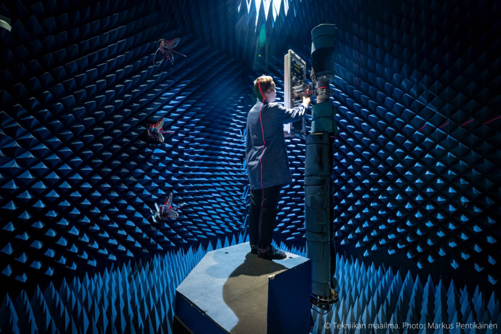
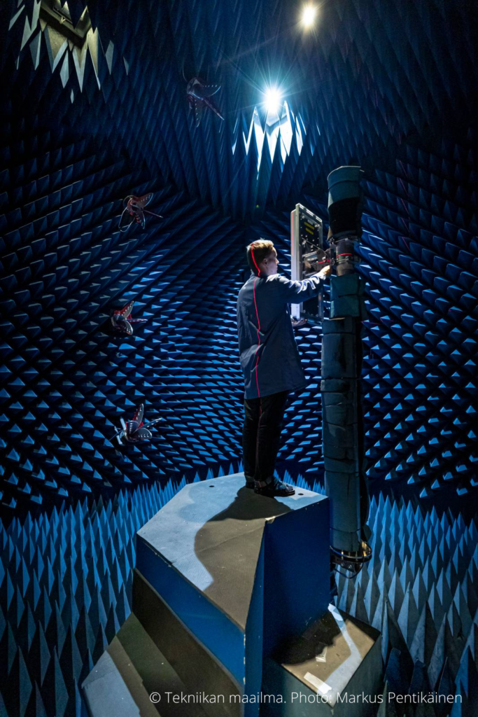
OTA testing is performed in one of our anechoic chambers. The device under test (DUT) is placed in a test environment, inside a test chamber, which is isolated from any outside signals. When performing an OTA test, the antenna performance is measured over the air interface. OTA testing measures the transmission power and sensitivity of a device. Based on these measures and maximum data throughput measurement, the radiation pattern of the antenna can be evaluated.
If you are interested how the whole OTA testing process is performed and want to know more detailed information, read our article What is OTA testing? – Everything you need to know about the process.
Antenna radiation pattern
The radiation pattern of an antenna represents the electromagnetic radiation, electromagnetic fields, around the antenna. Electromagnetic fields (EMF) are emitted or received from wireless devices when they are being used. There are different regional limits set by regulatory bodies for exposure to EMF. Electromagnetic fields consist of near field and far field regions, which are essential parts of our NF-FF transformation.
The near field and far field are regions of electromagnetic field around the transmitting antenna. Near-field, and the non-radiation behaviours associated to it, appear closer to the antenna. Far-field, with its electromagnetic radiation behaviours, are present at further distances.
The radiation behaviour of antennas is characterized by their far-field radiation pattern. The far field region of the antenna generally starts from the 2D2/λ (D = minimum sphere closing the antenna, λ = operating wavelength) distance from the antenna. This means that with large antennas, the far-field radiation pattern that must be known, can start from over 30 meters away from the antenna. The antenna size is not the only thing that affects to the distance of a far field; the frequency of an antenna will affect to it too. The higher the frequency is, the further away the far field will start if the size of the antenna remains the same.
With this calculator you can test from where the far field of different antennas would start. The measurement distance is the required size of the chamber. In some special cases, even the distance the calculator gives, is not sufficient enough and the distance must be even greater to get the far field radiation pattern.

Antenna Near Field & Far Field Distance Calculator
Wavelength:
Reactive Near Field Distance:
Radiating Near Field Distance:
Far Field (Greater Than):
NF-FF transformation
But where do we need the NF-FF transformation? Well, in anechoic test chambers, only the near field radiation pattern of large antennas can be measured. Typical test chambers are not big enough to be able to capture the far field condition of large antennas. If the far field condition of large antennas was measured in anechoic chambers, the chamber size should be huge. And huge anechoic chambers would not only cost a lot of money, but they would also take a lot of valuable space. This is where the NF-FF transformation steps in. With the help of NF-FF transformation we can convert the near field radiation pattern, measured in our chambers, to a far field radiation pattern.
Near-field to far-field transformation basically means, as its name suggests, transforming the near-field antenna radiation pattern to a far-field radiation pattern. The near-field characteristics are converted to far-field characteristics using software and necessary transformation algorithms. This mathematical transformation is possible to perform when we have measured the amplitude and phase in the near field.
NF-FF approach considerably reduces the required distance to get the far-field characteristics of an antenna. The transformation allows test labs to reduce the size of their anechoic chambers without losing any measurement accuracy.

Visualization of near field effect. Green represents far field and purple near field measurement result. (Verkotan Oy, 2021)
The NF-FF Transformation in practice
After the OTA testing is performed, and the near field antenna radiation pattern is known, we can convert the near field radiation pattern to the far field radiation pattern. After doing this, the antenna pattern can be calculated to any distance wanted.
The process of NF-FF transformation:
The probe correction
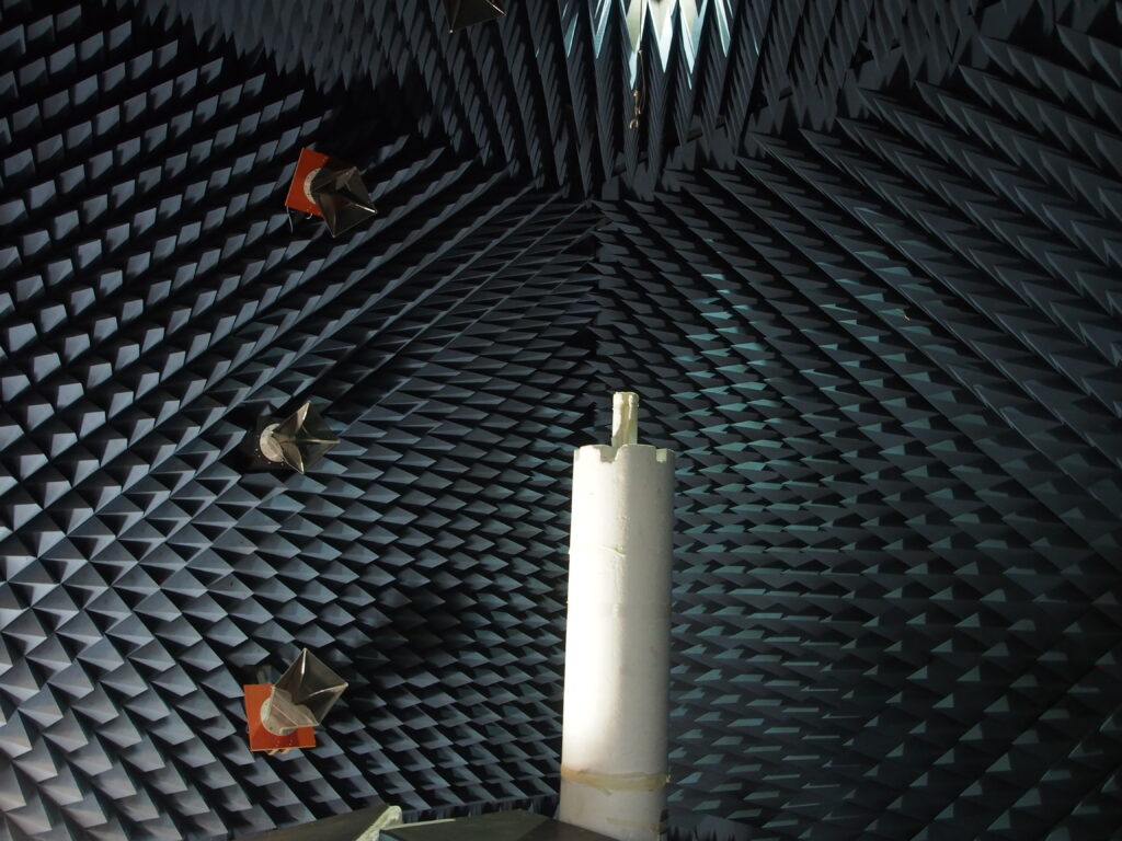
One important thing related to NF-FF transformation is the probe correction. Probe is the measuring antenna in anechoic chambers. Probe measures the performance of wireless devices. One challenge with the measuring probe is that it will see the device under test (DUT) from a certain solid angle. This will cause that the phase and the amplitude are not constant, and the measurement result will be skewed. This must be corrected in the near field to far field transformation. This correction is called the probe correction.
Probe correction is needed because the measured antennas are not isotropic, and they are not infinitesimal. They are big in size, for example one or two metres, which means that the distance from the probe to the antenna is not the same when measured in different parts of the antenna. The closer the probe is to the device under test, the more important the probe correction is. If the probe is far away from the antenna, the probe correction might not be even needed.

The probe correction is done by measuring the near field radiation pattern of the probe and converting it to the far field pattern with the NF-FF transformation. After that the software can utilize the measurement and take the measurement uncertainty into consideration.
The NF-FF transformation and Verkotan
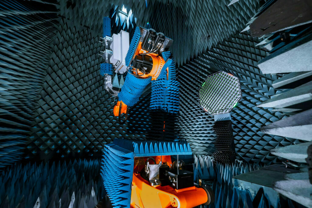
We use NF-FF transformation to measure the far field radiation pattern of large antennas, such as base station and point to point antennas. The NF-FF transformation as such can be used to measure the antenna characteristics of passive antennas. Measuring the far-field antenna pattern of active antennas requires a necessary algorithm and test equipment that can measure the amplitude and the phase accurately.
Passive antennas and NF-FF
Passive antennas are antennas that do not have any radios integrated in them. In passive antennas, radios are attached to the antenna through cables. When testing passive antennas, the test signal is sent to the antenna array from one of our testers. One way to test passive antennas is to measure each antenna port separately and create the beam after the testing by postprocessing using mathematical port weights and visualisation of results. Another way is to use a beamforming combiner device and produce the beam at the measurement time.
Nowadays technology has moved towards active antennas since passive antennas are not practical anymore due to the increasing amount antenna elements and cabling of them. Antennas might have over 60 antenna elements that all would need cabling in case of passive antennas. In addition, in passive antennas some of the power is lost in the cables, they consume a lot of energy and are big in size.
Active antennas and NF-FF transformation
Earlier, it has not been easy to evaluate the far field antenna radiation pattern of active antennas with the help of the NF-FF transformation. The reason is because there was no test equipment with which the phase of the active antennas could reliably be measured. Now there is, which enables us to define the far field antenna pattern of the active antennas with the NF-FF transformation. We have developed the world’s first algorithm that enables us to evaluate the far-field radiation pattern of active antennas. It is called active antenna NF-FF transformation.
With the help of the active NF-FF transformation, Verkotan can measure the far field radiation pattern of active antennas by using the NF-FF transformation. NF to FF method is based on Verkotan’s in-house developed method for amplitude and phase extraction from the active signal, including 5G signal, which enables mathematical transformation of the measured near field data to the far field.
Active antenna testing has its own challenges. Active antennas contain radios which makes the testing more complicated. Radiation pattern of active antennas can be measured when radio is receiving or sending signals. Testing of the active antennas must be performed in an active mode, which means that the DUT is put on a signalling mode and antenna array and radio unit work as they would in real life. Active antennas are also relatively new, so there are not many solutions developed for testing them. The test results of active antennas are close to real life experience because the antenna is in an active mode, signalling the same kind of signal as it would in real life conditions.
Active antennas also often use beamforming technique. In many cases, the beamforming orientation is done digitally with a software, and it cannot be verified by the traditional passive NF to FF method. Nevertheless, the active NF-FF transformation we have developed enables us to verify that every aspect of the antenna elements and the whole radio unit is working correctly.
The active NF-FF transformation has been done by creating our own passive NF-FF implementation, in which the probe correction is already taken into consideration. The active NF-FF transformation has been generated from the passive NF-FF implementation by using signal processing and software radios. This NF-FF modification allows us to measure active antennas.
The only requirement from the antenna is that it must send a recurring signal so that we are able to evaluate the antenna radiation pattern. We can measure, for example, 5G beamforming antennas with this active NF-FF transformation.
Alternative ways to create the far field condition
Near field to far field transformation is not the only way to get the far field radiation pattern of an antenna. Next, we will go through three alternative ways to get the far field radiation pattern.
- RF OTA anechoic test chamber
The indoor anechoic chamber refers to a chamber in which the measurement distance is sufficiently large so that the DUT is tested in a far field condition, defined by the Fraunhofer distance. It depends on the DUT size and frequency if the far-field antenna pattern can be achieved without NF-FF post modification. With smaller antennas, whose far field starts closer to antenna, the far field condition can be attained without any post modification straight from our test chambers.
- Compact antenna range
One way to create the far-field condition is Compact Antenna Test Range (CATR). The compact antenna test range test system utilizes a radio frequency reflector. The radiated signals are reflected from a parabolic reflector to create the far-field condition at distance shorter than required by the Fraunhofer criterion.
- Plane Wave Synthesizer
The far field condition can also be created with the plane wave synthesizer. A plane wave converter is a phased antenna array, which acts as a replacement for a traditional test system antenna. The test signals are fed through the antenna elements of the converter and the amplitude and phase of each element in the array is controlled so that a plane wave field is produced at the test zone.
Verkotan services
We provide FR1 Active Antenna Testing Service according to 3GPP TS38.141-2, 6.2 radiated transmit power and 7.2 OTA sensitivity for base stations and ancillary equipment. We are one of the first commercial laboratories providing this high-quality accredited test service for 5G NR OTA testing certification.
We have two independent test methods to test radiated transmit power and OTA sensitivity. These two test methods are our unique active near field to far field antenna test system and plane wave synthesis active antenna test service using R&S PWC. By providing active antenna test service, we support our customers in their product development phase and in getting their type approvals for the market entry.
References
https://www.antenna-theory.com/basics/fieldRegions.php#:~:text=Far%20Field%20or%20Fraunhofer%20Region%20The%20far%20field,antennas.%20We%20will%20start%20with%20the%20Far%20Field.
https://www.tutorialspoint.com/antenna_theory/antenna_theory_radiation_pattern.htm
https://www.ei.tum.de/hft/forschung/near-field-antenna-measurement-and-transformation-techniques/near-field-antenna-measurement-and-transformation-techniques/
Follow our social media channels to keep up with the latest news in the world of wireless technology.