


Millimetre waves and 5G
5G is a term we all have heard of. It is a technology that will improve the speed and latency of networks and connected devices. It allows more devices to connect to the network at the same time due to improved capacity, and has a shorter response time, which allows remote controlling without any delays. More efficient bandwidth utilization in 5G helps operators to gain more capacity on limited frequency sources.
5G will expand the operating frequencies of mobile networks above the frequencies used by previous generations, such as 2G, 3G and 4G. The technology developed for 5G includes Frequency Range 1 (FR1) and Frequency Range 2 (FR2). FR1 includes bands below 6 GHz, and FR2 includes bands above 24 GHz and extremely high frequencies above 50 GHz. Radio waves operating in FR2 are typically called millimetre waves. Millimetre waves are operating at high frequencies, and the higher the frequency is, the smaller the waves are. That is why millimetre waves are called millimetre waves; their length varies from about 1 to 10 millimetres.
Millimetre waves are going to be used in commercial 5G networks in Europe within a couple of years. Currently USA is pioneering at using millimetre waves in commercial 5G networks. One reason for using millimetre waves in 5G networks is that nowadays wireless networks are crowded because more and more devices are using the same bands at the same radio frequency spectrum. This means that there is less bandwidth per person, which slows the data speed down. This problem is solved by using a radio spectrum that has not been used; in the case of millimetre-wave 5G it means the frequencies from 24 GHz to 300 GHz. 5G technology will still use lower frequencies in addition to higher frequencies to be able to work together with earlier technologies.
Challenges with millimetre waves
There are certain challenges with millimetre waves. One of the challenges is the short wavelengths of the waves, since the smaller the waves are, the harder it is for them to travel through obstacles. Even weather conditions can affect millimetre wave propagation. This problem is solved by installing more base stations. Dense base station networks allow 5G base stations to operate at low transmission power.
Indoor Coverage
One challenge with millimetre waves is their indoor coverage. Higher frequencies cannot penetrate building structures and walls as easily as lower frequencies. This has posed challenges to 5G networks since about 80% of data consumption happens indoors. This problem can be solved by installing indoor small cells that will improve the connections.
Coverage area
The short length of the waves means that also the coverage area of 5G millimetre wave base stations is small. With point-to-point antennas, millimetre wave base stations’ operating distance is about one kilometre and with mobile devices the distance is even shorter. Whereas with traditional base stations, operating below 6 GHz, the coverage area may be even 35 kilometres. This is one reason why 5G networks are first built in highly crowded places, such as train stations, different stadiums, and city centres. In highly crowded places 5G networks’ cost-benefit ratio is worthy because there are a lot of users in a relatively small area.
For 5G networks to work properly with user equipment (UE), user equipment must use the beamforming technology, in addition to the beamforming technology used in the 5G base stations. Without the beamforming technology, the coverage area of 5G base stations would be so small that base stations should be located extremely close to each to others. Beamforming allows forming the connection between the base station and UE at further distances.
Fact: If satellite dish antennas’ size is kept constant, the free space loss of radio link is the same despite the used frequency. But with millimetre waves any obstacles, like rain and leaves, between the antennas will affect to the functionality.
If you are interested how beamforming antennas work and how beamforming antennas are tested, you should read our Beamforming Antennas –How they work and are tested? -article.
Challenges with testing the millimetre waves
Millimetre waves also pose new challenges for testing millimetre wave connections: the measurement power decreases because the transistors operate at a lower efficiency as the frequencies increase. In fact, in practice no transistor operates above 300 GHz. In addition, attenuation increase at higher frequencies due to air interface and cables. Also, accuracy requirements and mechanical accuracy requirements become more demanding as the waves are so short in length.
Over-the-Air testing of millimetre waves
OTA testing is performed to measure the wireless performance and reliability of a wireless devices via the antenna. The radio signals of the wireless devices are examined in various ways by simulating the use cases in real-life conditions. The device under test (DUT) is set down in a test environment, inside a test chamber, which is isolated from any outside signals. The goal is to verify the wireless performance and that the device responds as intended to the test conditions.
To understand the whole OTA testing process more comprehensively, read our Wireless Performance and OTA testing – Why testing your wireless device is important? -article.
Verkotan can perform millimetre wave measurements to passive antennas and active TX antennas. Next, we will go through passive antenna testing and active TX antenna testing for millimetre waves.
Passive millimetre wave antenna testing
Passive antenna testing uses an Over-the-Air, OTA test method, where the test signal is fed directly to the antenna array. The radio frequency signal coming out from the antenna array is then measured. The device under test typically does not contain any active radio unit. This makes passive antenna testing straightforward and delivers easily comparable results. Passive antenna performance measurements mainly entail measuring characteristics such as gain, directivity, efficiency, side lobe ratios and other parameters defined by BASTA specifications . Typically, either 2D cross sections or full 3D pattern is measured.
There are two ways to perform passive antenna testing. Either each antenna port is measured separately, and the beam is formed in post processing using mathematical port weights. For FR2, more common way to measure passive antennas is to use an analogue beamforming device to produce the desired beam at the measurement time.
Verkotan FR2 passive antenna services
New wireless devices and new technologies will require higher speed and better capability to transfer data. Verkotan OTA FR2 test service will serve the purpose of high-performance qualification. We offer passive antenna testing for FR1 and FR2. Our testing capability covers frequencies 400 MHz up to 53 GHz. The testing for FR2 is performed in our anechoic chamber by utilizing direct far-field transformation methodology.
The higher the frequency band of the radio links is, the more challenging and greater directivity is needed to compensate increased path loss of the radio link. Beam steering is used in sending and in receiving ends to increase coverage area of beamforming. Anechoic chamber provides sufficient attenuation of disturbing reflections in FR2 measurements, and the results will be accurate antenna beam patterns.
Verkotan test chambers provide a shielded environment so that radiated signals of known power and direction can be generated and measured in a controlled environment. Antenna testing is important step to do to reach the high performance in the 5G communication.
Evaluated antenna parameters typically include:
• Gain
• Beamwidth
• Azimuth Beam squint
• Cross-polarization ratio
• Tilt accuracy
• Front to back ratio
• First upper sidelobe suppression
• Efficiency
Also, other parameters can be measured according to customers wishes. We can test small base stations, radars, mobile devices, point to point microwave antennas, et cetera.
Active antenna TX measurements
For testing active antennas, a similar environment is used as testing passive antennas. However, in active antennas, the antenna ports are embedded in the device. Most of the RF signal generation steps are performed in the radio unit itself. The testing is performed while the DUT is in active mode, so that the DUT is sending a recurring signal, and the radio unit and antenna array operates as they would in a real network.
Due to the tight integration of the radio unit and active antenna array, more and more parameters that were traditionally measured in a conducted test setup must be tested in radiated conditions. On the FR1, typical parameters measured over the air include the transmitted power and sensitivity of the base station. In addition to this, on FR2 all the RF parameters must be evaluated over the air. These include parameters such as EVM, ACLR, blocking, selectivity, spurious emissions, among many others.
Our active antenna OTA testing capability covers frequencies up to 42 GHz. We can test small base stations, radars, mobile devices, point to point microwave antennas, et cetera.

Antenna pattern analysis tool
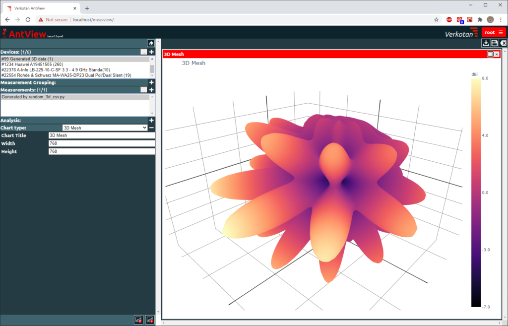
We have also developed a tool with which you can easily analyse your antenna pattern measurements. Our in-house developed antenna pattern measurement analysis and visualization tool AntView® makes analysing, comparing, and storing antenna measurement results easier and more efficient. It enables fast antenna characteristics analysis. With AntView®, you can easily compare multiple antenna measurement results and present them in an easy-to-understand format with colours, graphs, and e.g. BASTA parameters.
If you are interested, we are offering a free demo access to our AntView® software. The process how to get the demo access is very straight forward. Fill out the form to request access to the demo and in three business days we will send you the username and password for AntView®. After getting the access, you can start exploring the software!
By getting the demo access you are not obligated to anything. We do not require any information other than your name, e-mail, phone number and a company name.
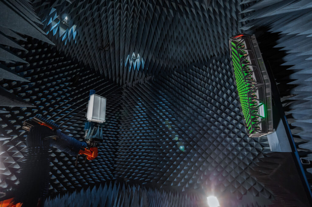
Our millimetre wave testing chamber
Our millimetre wave testing chamber has a 7,2 metres measurement distance. We can measure antennas operating at 2 GHz to 53 GHz frequencies. The maximum size of the antenna element depends on the frequency: with higher frequencies the maximum DUT size is smaller. In this chamber, the maximum size of the DUT, in the frequencies from 2 GHz to 53 GHz, varies from 15cm to 75cm. Our active antenna OTA testing capability covers frequencies up to 42 GHz and passive antenna OTA testing capability covers frequencies up to 53 GHz.
Additional information
If you have any further questions, do not hesitate to contact us. In addition to 5G millimetre wave testing, we provide OTA testing for equipment using 2G – 4G technologies. Our service portfolio also includes many other OTA services, such as GNSS testing, IoT OTA measurements, Mobile Device OTA testing up to 5G and many other tailored test solutions.
Do not forget to check our RF exposure services either if you are a radio device manufacturer. We provide accurate and flexible RF exposure services. To understand the best method to evaluate the RF exposure of your device read our comprehensive Four ways to show RF exposure compliance -article.
References
https://jyx.jyu.fi/bitstream/handle/123456789/64032/1/URN:NBN:fi:jyu-201905172659.pdf
https://spectrum.ieee.org/5g-bytes-millimeter-waves-explained
https://www.stuk.fi/aiheet/matkapuhelimet-ja-tukiasemat/matkapuhelinverkko/5g-verkon-sateilyturvallisuus
If you have any further questions do not hesitate to contact us! We are always ready to help you.
Follow our social media channels to keep up with the latest news in the world of wireless technology.