


Contents
- Evolution of wireless technologies
- Automotive radars in high frequencies.
- Entry100GHz project to reach the 100 GHZ frequency area
- Wireless testing solutions for high frequencies
- Request More Info
Evolution of wireless technologies
The evolution of the wireless technologies during the past 40-50 years has been tremendous. Especially the evolution of the cellular radio technologies and related infrastructure and short-range radios (Bluetooth, Wi-Fi etc.) have virtually changed the whole world and the lives of people. The evolution has included the development of vast number of technologies including modulation technologies, source and channel coding technologies, the exponential growth of computing power, Multiple-input-Multiple Output (MIMO) technologies, protocols, and access methods, etc.
The amazing development in displays, semiconductor technologies, RF-technologies and other hardware technologies has made it possible to implement these new methods into new innovative communication products. The trend has been from voice centric communications to all-data communications with high data rates and high channel capacity and “internet” type of IP network architectures.
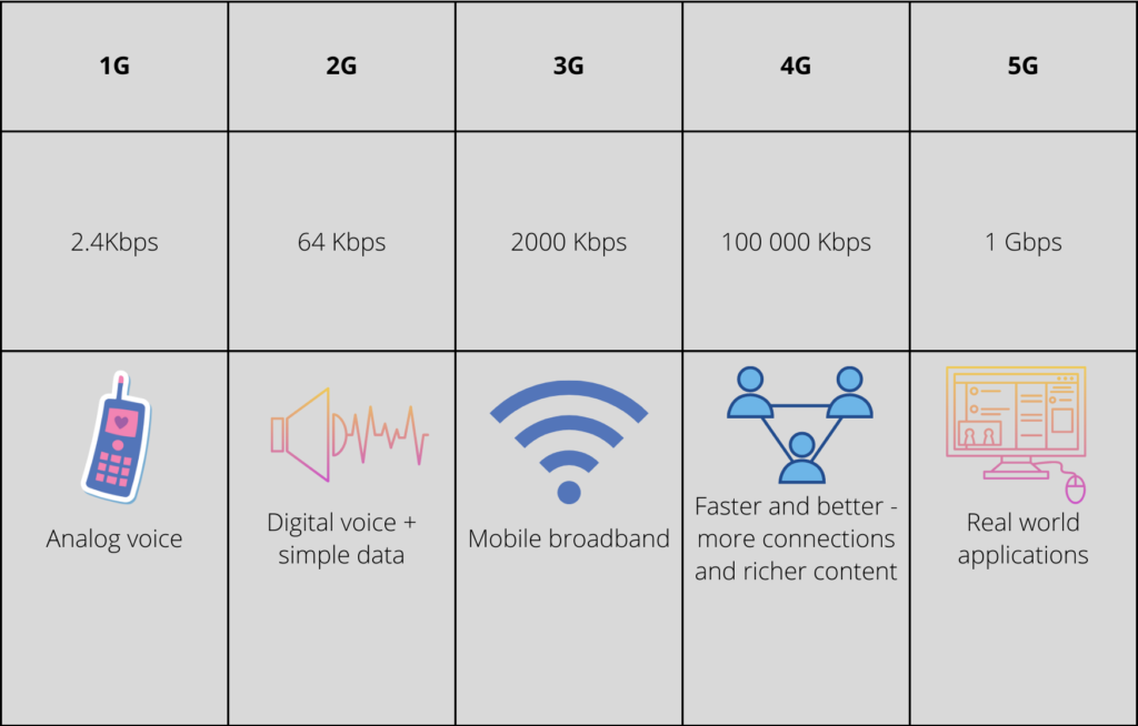
Towards higher capacity and higher data rates
In order to gain higher capacity and higher data rates, wireless industry is seeking technologies and solutions for higher frequency bands. This enables wider channel bandwidths and therefore higher data rates and higher network capacity.
Examples of different bandwidths in different cellular technology generations
- In 2G GSM technology the bandwidth was 200 KHz and frequencies were below 2 GHz
- In 3G technology the bandwidth is 5 MHz and frequencies up to 2.6 GHz
- In 4G technology the bandwidth is flexible ranging 1.4 MHz – 20 Mhz and frequencies up to 3.6GHz
- In the most recent 5G technology the bandwidths are flexible and may be even hundreds of megahertz. Below 7GHz frequencies’ maximum bandwidth is 100 MHz. For over 28 GHz frequencies it can be even 400 MHz. The frequency bands of 5G are 7 GHz at the lower frequency range and in the higher frequencies they range from 28 GHz to 53 GHz.
In addition, new carrier aggregation technologies have been developed to provide higher data rates also at lower frequencies. In this context, carrier aggregation means a technology in which several channels are “bundled” and used to convey data for a single device. Therefore e.g., mobile wireless technologies generation after generation are reaching higher frequencies, which enables wider channel bandwidths.
The backhaul industry is now taking major technology leaps to utilize frequency bands of close to 100GHz and beyond that. Wireless backhaul links are connecting cell sites towards core networks in mobile networks. In many cases microwave radio links are used for this purpose. This will enable wider bandwidths and higher capacity backhaul links and guarantee service after increased capacity needs.
Shorter wavelengths and smaller antennas
Another benefit higher frequencies offer is that because of the short wavelength, a single antenna element is small (e.g., magnitude of wavelength). This enables the manufacturing of compact antenna arrays which can produce sharp beams. In addition, the direction and the form of the beam can be controlled by properly phasing the antenna elements of the array. Antenna arrays can include e.g., 64 (8×8) antenna elements with 2 polarizations.
Beamforming antenna technology has opened totally new ways of increasing the performance of mobile base stations. Beamforming antenna technologies can be applied also at low frequencies, but the physical size of the array becomes large. This is because in the lower frequencies the wavelength is longer and therefore the optimal size of the antenna element is larger. These kinds of large arrays at lower frequencies are used e.g., in radio astronomy and other scientific applications.
Challenges with higher frequencies
Higher frequencies don’t only offer benefits, but they also set technological challenges. One challenging fact is that the atmospheric attenuation increases radically at higher frequencies. Also, penetration losses (e.g., walls, windows etc.) increases significantly depending on the materials. To compensate high pathlosses, highly directive antenna arrays, which are forming very sharp beams to wanted directions, are used. Beam steering antenna technology will be essential at mm-wave region. Beam steering in mm-wave region is used in both base stations and user equipment (UE) in order to overcome high path loss problems. In mm-waves there can be even hundreds of antenna elements in a single array.
Very short wavelengths also set other type of challenges e.g., in the manufacturing of the antennas, convoying the signals and the electronics. These kinds of challenges are faced especially when frequency regions of 100 GHz are entered. The short wavelengths cause very tight mechanical tolerances and good temperature compensations. For this reason, in practice, devices usually have closed loop calibrations implemented to ensure phase accuracy.
In addition, one very important factor is to be considered: the Specific Absorption Rate (SAR) limitations. If there is a possibility that very sharp and high-power density beams can hit tissue e.g., an antenna close to the body, it may be possible to exceed SAR limits. Therefore, it is important to take this into consideration and make proper SAR measurements already in the development phase. Read more about Verkotan’s SAR services from our RF exposure testing services page.

Automotive radars in high frequencies
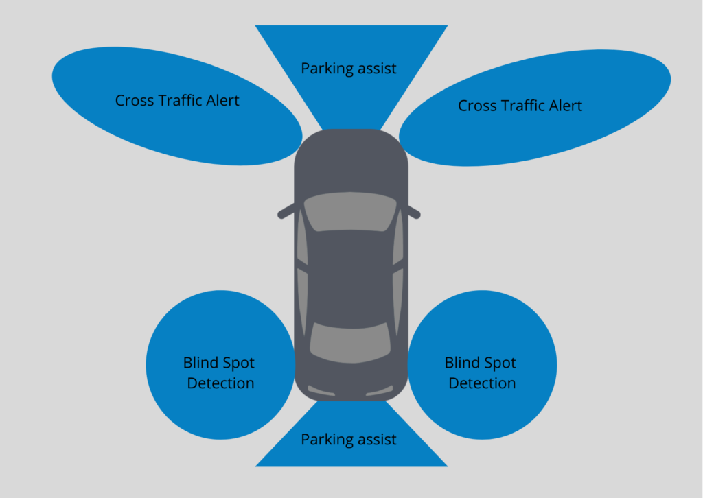
Sensors are a growing application area. Especially different kinds of radar-based sensors are used very widely not only in traditional aviation and maritime areas but currently also in automotive applications. Currently the automotive radar bands range from 24 GHz to between 76 GHz and 81 GHz. The bands depend to some extent on their geographic location. In Europe the 24 GHz band is phasing out in 2022.
Development of different kinds of driver assistance systems (ADAS) and autonomous driving systems have increased the need to observe the environment around the vehicle. In the coming years, ADAS systems are becoming mandatory in cars in the EU. There are several dedicated radar applications in a single vehicle, for example adaptive cruise control, blind spot detection and all different kinds of collision avoidance systems. We at Verkotan are ready to help you to measure the OTA performance of radar beams.
Automotive radars, which operate at 77 GHz and 79 GHz, are one of the key business drivers in the frequency range from 75 GHz to 100 GHz (W band). Wireless communication applications at these higher frequencies possibly start to emerge after 2025. It is possible that the first solutions operate in unlicensed bands and may even be in the short range consumer application domain.
These higher frequency bands are also studied for coming 6G radio systems and its infrastructure. 6G is now in the research phase and standardization activities may start after 2025. First commercial higher frequency bands are expected to emerge around 2030.
Entry100GHz project to reach the 100 GHZ frequency area
Verkotan is participating in the ENTRY100GHz project, which is also part of international Celtic-Next research program. In this project, four universities and 12 companies from Finland, Sweden, and South- Africa are studying radio technologies in the 100 GHz frequency area. In the future wireless systems, the target is to achieve ultra-high data rates (approaching 100 Gbps) for various wireless applications. This requires instantaneous bandwidths of several GHz, which is only available in the sub-THz-wave (~100 GHz) frequency range.
In the 100 GHz frequency area, there are several challenges to be addressed.
- The radio propagation loss is very significant in sub-100GHz frequencies. One way to address propagation loss and limited output power effects is to use large active beamforming phased array antennas. This technology can produce sharp steerable beams with high RF power in the right directions.
- Efficient RF power generation is challenging
- Very small wavelength and related phase shift effects require new design paradigms. The challenge of small wavelengths can be addressed with integration technologies and new antenna manufacturing technologies.
Due to very small wavelengths and impacts of both external and parasitic factors, calibrations of beams (direction, shape etc.), both uplink and downlink, become more crucial than in the lower frequencies. Both measurements based on initial calibration and some feedback based on real time calibration may be needed. New methods, algorithms and designs are needed to address the challenge. This project enables Verkotan to grow its competencies in this area and later develop its products and services to best suit our clients. In this project, full transceiver technologies are studied including transmitter, receiver, antennas, filtering, waveforms etc. Real demonstrator systems are built to enable verification and antenna measurements.
In ENTRY100GHZ Verkotan is studying the required antenna measurement technologies, system performance characterization and beam calibration methods. Because of very short wavelengths many external factors impact performance, and it is very difficult to predict the real performance only e.g., with simulations. Therefore, antenna measurements and characterization of beams play a crucial role. For these purposes Verkotan is considering of testing a new chamber in which testing of frequencies over 110 GHz could be reached.

Wireless testing solutions for high frequencies
The continuous development of wireless technologies both sets new challenges and opens new opportunities for companies providing antenna testing. Keeping in pace with the technology development requires continuous investments to test systems. Currently frequency bands in FR1 (< 7 GHz, channel bandwidths 5 – 100 MHz) and FR2 (24 GHz – 52 GHz, channel bandwidths 50 – 400 MHz) ranges have been allocated for 5G systems. Unlicensed communication systems and RF sensors (e.g. automotive radars for ADAS systems) are emerging with frequency ranges from 50 GHz to 100 GHz. These form the key drivers for Verkotan’s current research and development activities in antenna measurement technologies with its partners and customers to meet the new requirements.
Test system development for more efficient antenna measurements
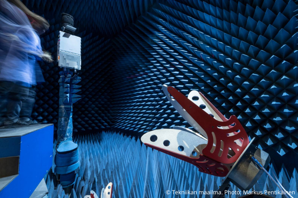
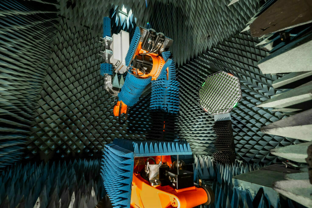
Verkotan has developed own unique near-field to far-field (NF-to-FF) software and test system. In this antenna measurement method the antenna’s near field, both phase and amplitude, is measured by using probe antennas and with spherical sampling and the far-field is computed with transformation SW. This enables far-field antenna measurements of quite large antennas and antenna arrays in a reasonably sized anechoic measurement chamber.
The system can be applied in the whole FR1 range for both active and passive antennas and both for downlink and uplink. Especially Verkotan’s active antenna measurement capability is unique. Precise industrial robot-based positioning system enables the possibility to measure antennas up to a size of 3 meters and a weight of up to 120 kg. The same system is also used in FR2 range for passive antennas. More detailed description about the testing of beamforming antennas can be found in our article Beamforming Antennas – How they work and are tested ?.
We have also a new chamber that enables antenna measurements of passive antenna radiation patterns up to 53 GHz. In mm-waves the antennas are typically smaller, therefore a tailored accurate positioning system is used. Maximum antenna size of the antennas in this chamber in the frequencies from 2 GHz to 53 GHz, varies from 15 cm to 75 cm depending on the frequency: in higher frequencies the antenna size is more limited. All typical antenna parameters can be evaluated: gain, beamwidth, cross-polarization ratio, tilt accuracy, front to back ratio, sidelobe suppression, efficiency etc. For active antennas TRP radiated power can be measured for up to 44,5 GHz. More detailed description about mm-wave OTA testing can be found from here: Over-the-Air testing of millimetre waves – Verkotan
AI4Green for more efficient computing methods
Verkotan is currently participating in AI4Green international Celtic-Next research projects. In this project Verkotan has studied NF-to-FF improvements to speed up the computing and visualization of large amounts of antenna measurement data. With large beamforming arrays computing effort can be significant since a lot of data is collected. In that project Verkotan has also done antenna trial measurements of scalable FMCW Frequency-Division Multiplexing MIMO Radar which has been developed by VTT. The radar is operating at 60 GHz frequency, and it applies 8×4 MIMO technology with 4 TX and 8 RX.
Request More Info
If you need more information, Verkotan is always happy to provide more detailed information. We are always ready to make a proposal about how we can help you to verify the performance of your device in the global environment. Visit our Over-the-Air wireless performance testing and RF exposure testing service pages to find more information about our main services.
With our help, you can offer the best user experience for your customers.
References
Rishabh Aggarwal, 2018, Wireless Communication: Evolution and Advance Wireless Communication | Semantic Scholar
www.KFZ.net
Follow our social media channels to keep up with the latest news in the world of wireless technology.
If you have any questions or need assistance, contact us. We are happy to help you!